Creating patch panels from scratch in Device42: an example
This page presents a step-by-step approach to creating patch panels, from initial setup to end result.
The Goal
The following example is simple in nature but covers the basics of adding patch panel connections in Device42.
The end goal is:
- Patch
Panel Ais connected to PatchPanel B. - Patch
Panel Ais patched toswitch-01. - Patch
Panel Bis patched to devices in the same rack as patchPanel B.
This will provide our devices with connectivity to switch ports.
Create Patch Panel Models
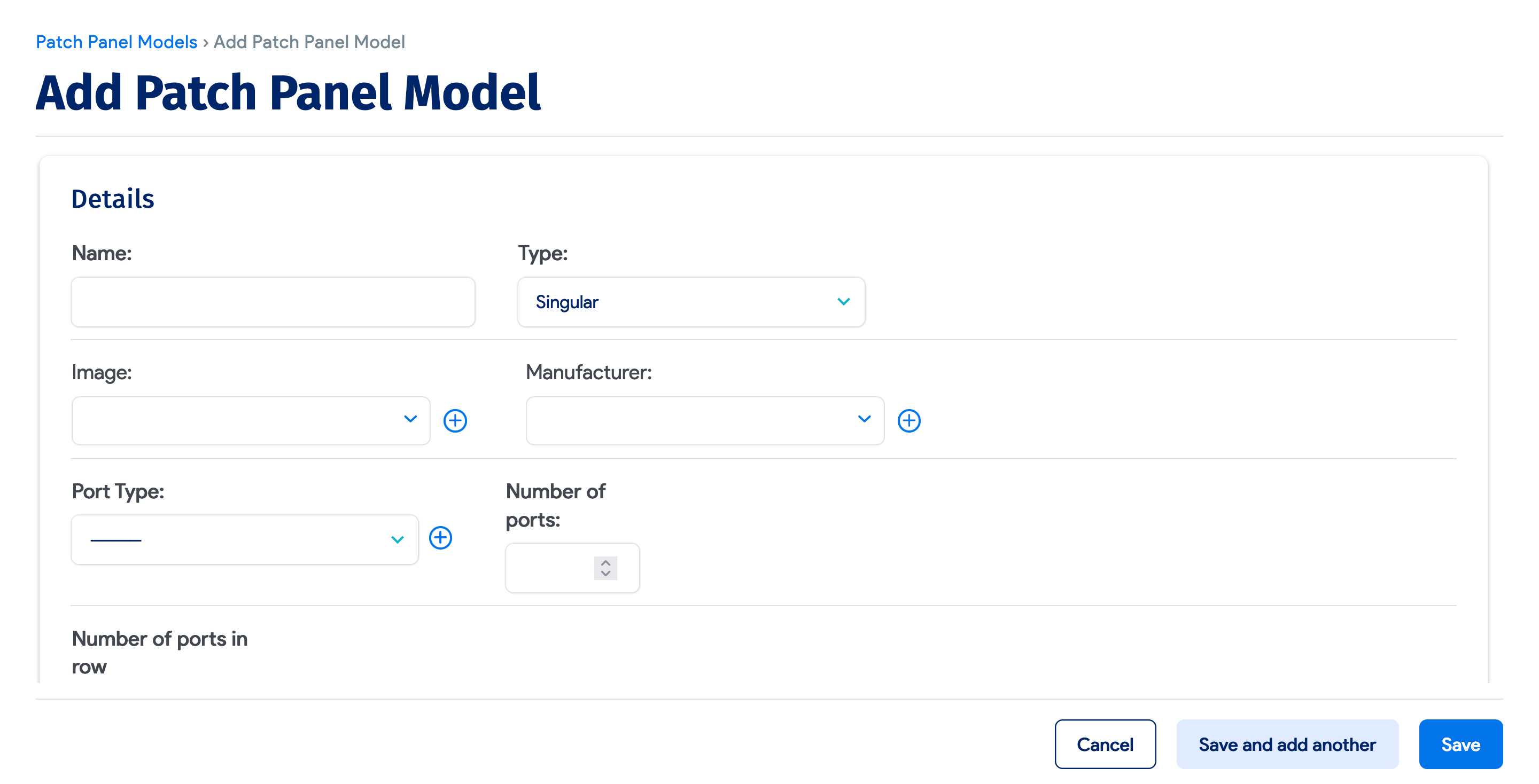
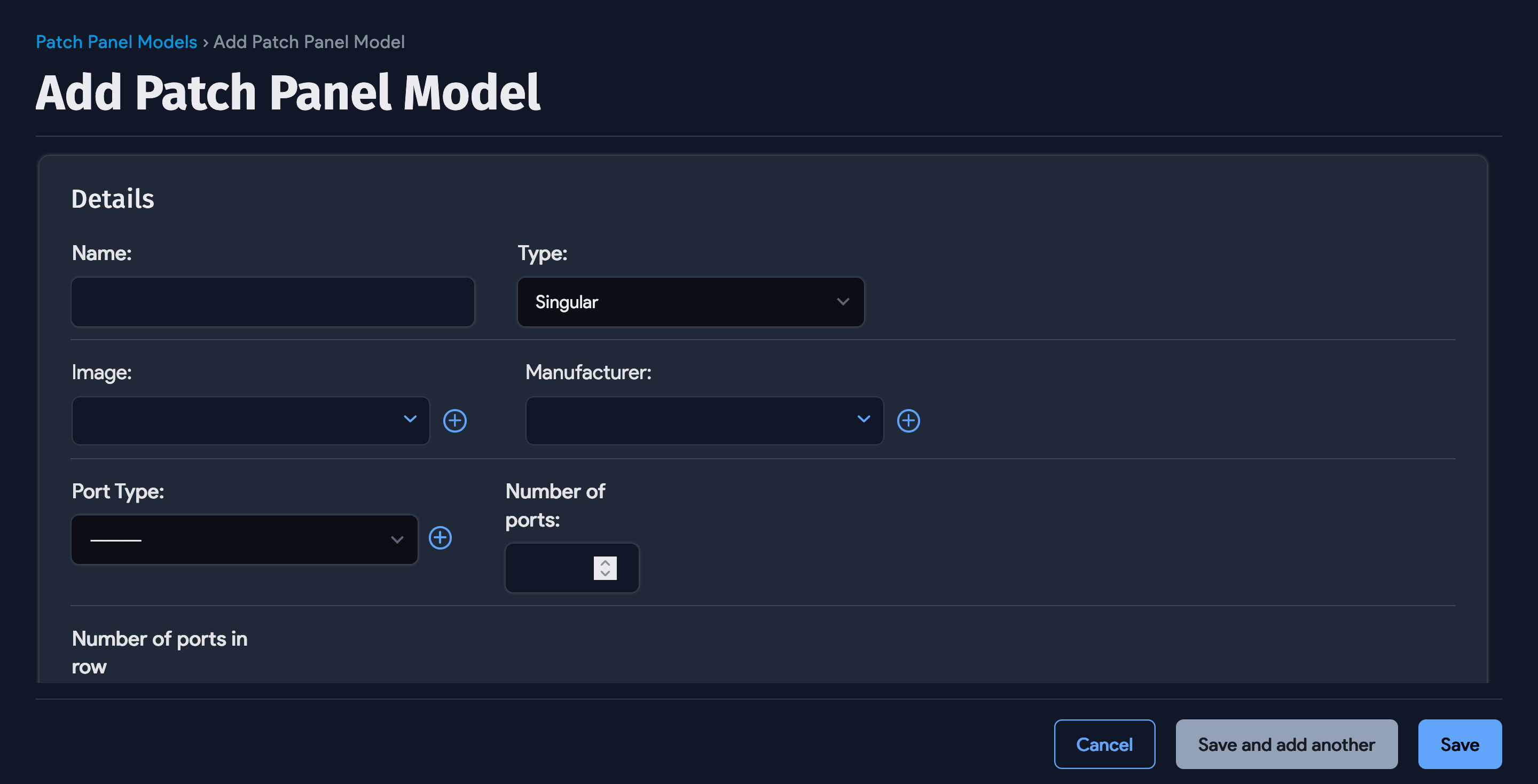
Before we add the patch panel, we need to create the template. In this example, this is a single patch panel with 48 RJ-45 ports.
- Go to Resources > Assets > Patch Panel Models > Create.
- Enter the details for the model, including a name, port type, and number of ports.
- Save the patch panel model.
Create Patch Panels
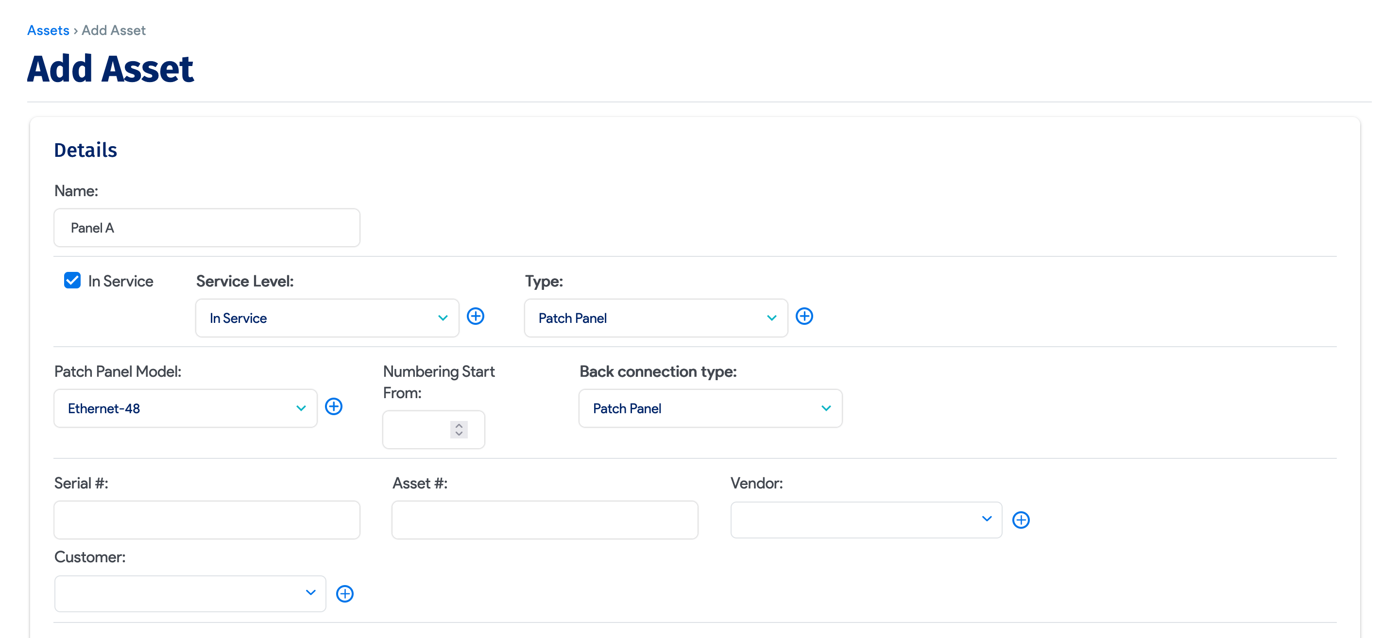
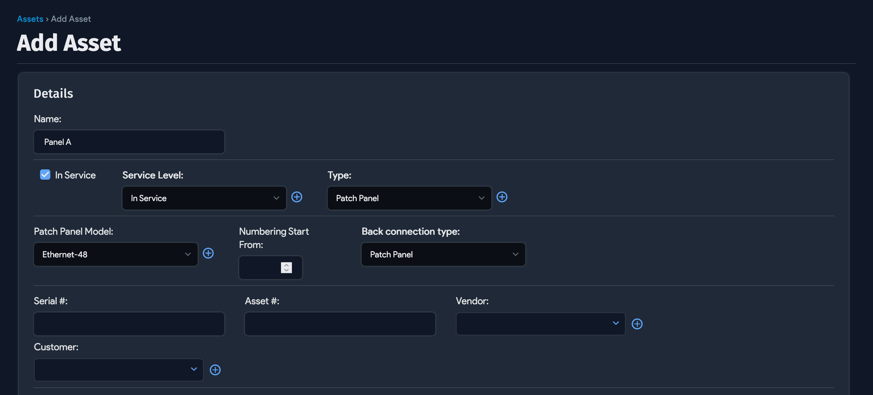
- Go to Resources > All Assets > Create.
- Name it
Panel A, select Patch Panel as its Type, and choose the model created above. - Click Save.
Repeat the same steps for Panel B, changing only the name to Panel B in Step 2.
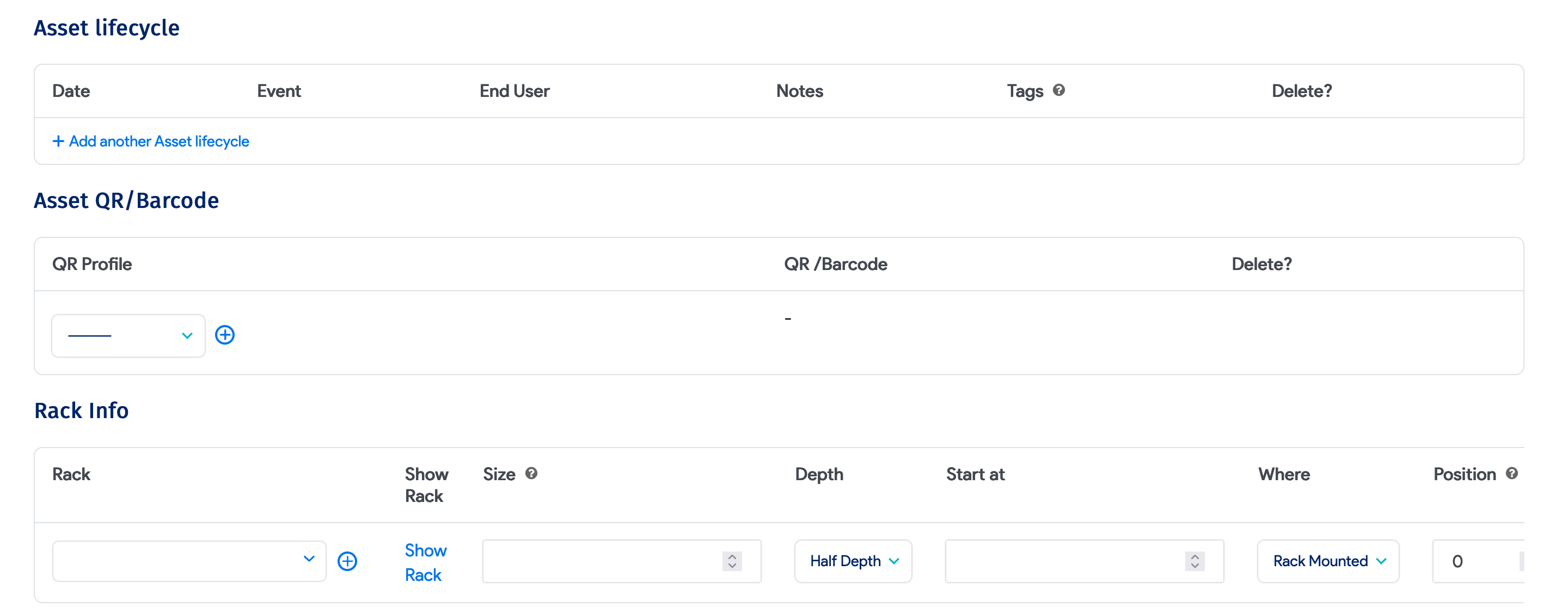
You can also specify the building and storage room, and add tags and images of the front and back.
Add the Back Connections or Termination
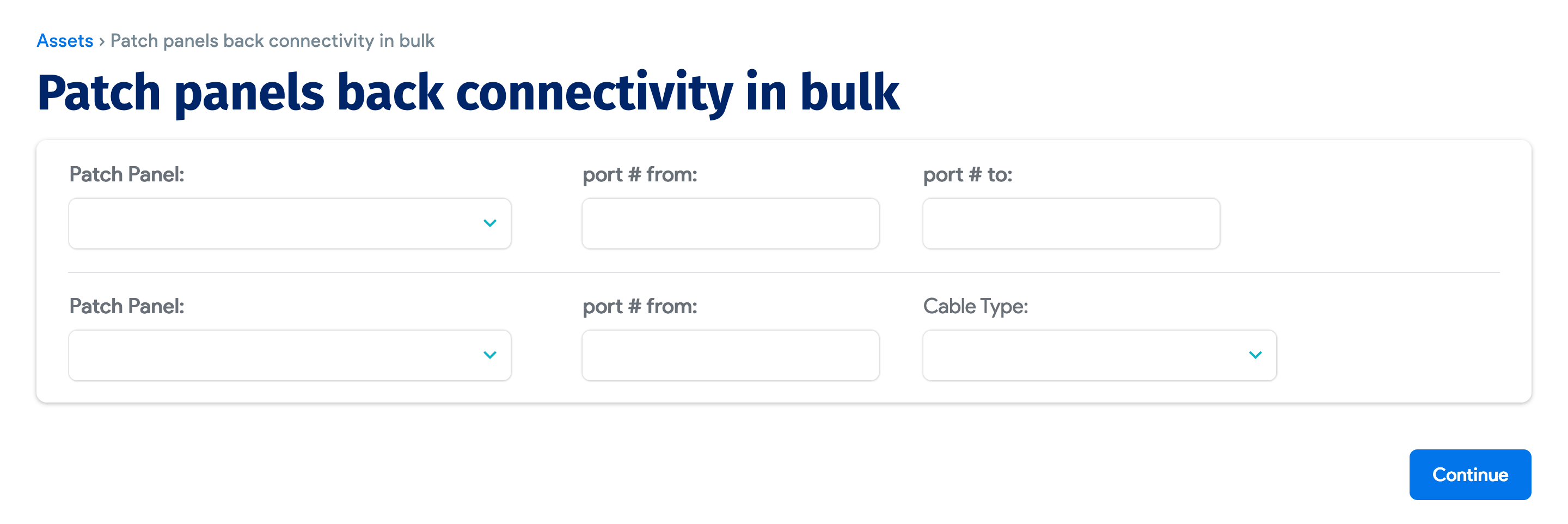
- Go to Tools > Templates & Bulk Operations > Panel Back Connectivity.
- From the dropdown, choose Patch Panel A, then enter
1for the beginning port # from and enter48for the port # to. Then, select Patch Panel B, and enter1for port # from, and optionally, select the Cable Type. - Click Continue.
Now, Panel A and Panel B are connected to each other.
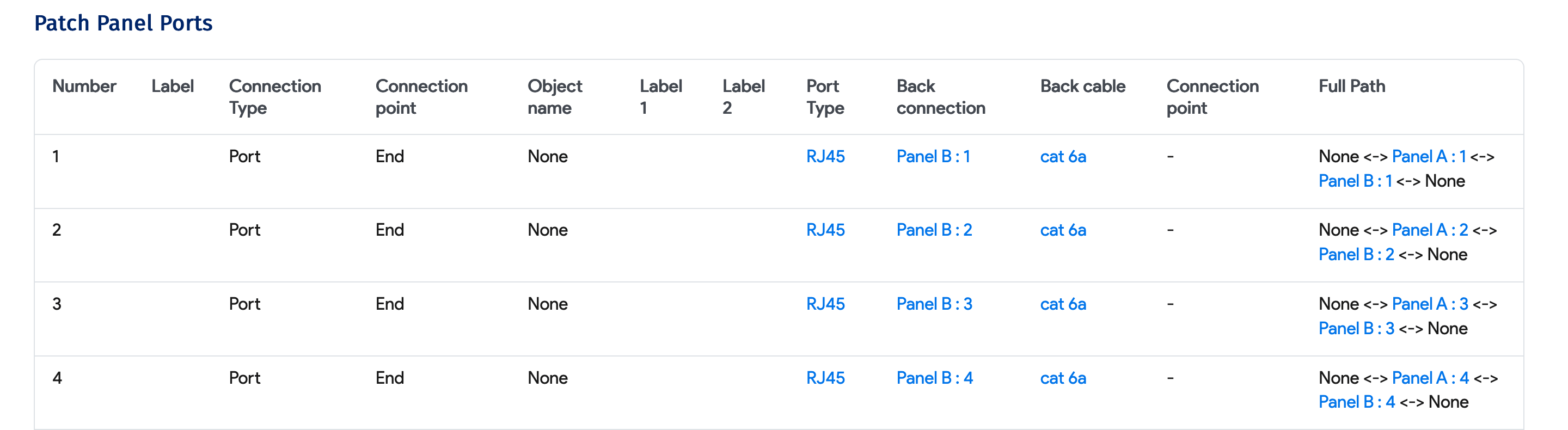
Patch Switch Ports to Panel A
- Go to Tools > Templates & Bulk Operations > Import/Export (xls).
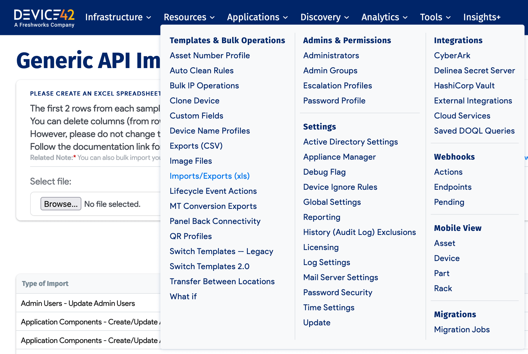
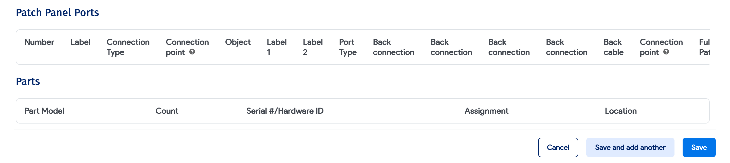
- Scroll down to Patch Panel Ports.
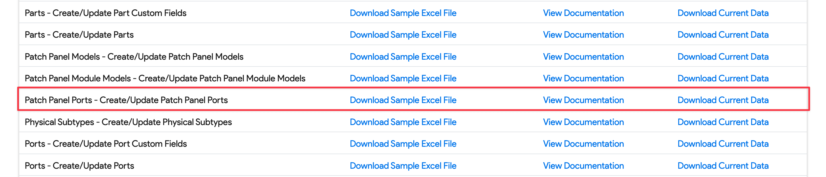
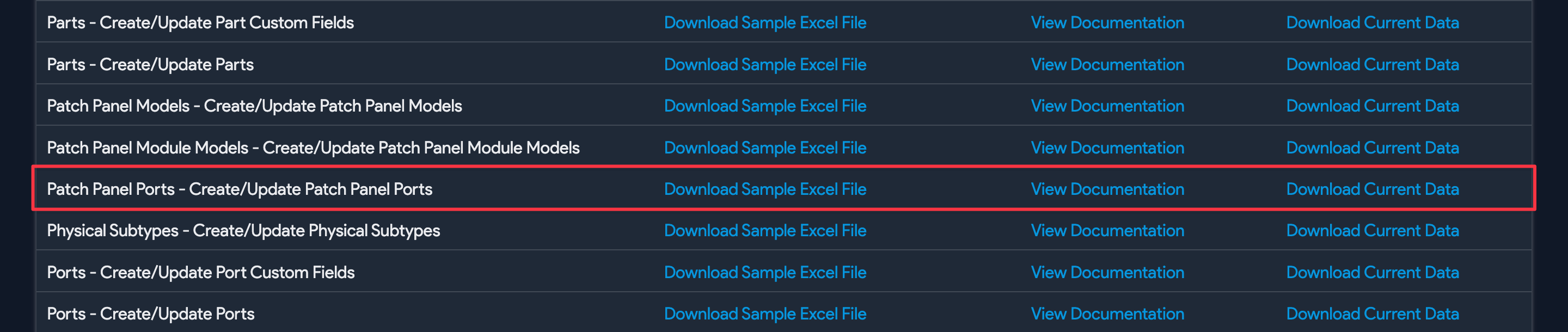

In this example, ports from switch-01 are patched to Panel A. (You can create switch ports in bulk using switch templates, as discussed under Switch Templates.)
The tedious way to do this is to add each switch port to each panel port. Instead, use the recommended API Excel import option as follows:
- Download the sample Excel file from Create/update Patch Panel Ports on that page.
- Check that the columns look like this: number | patch_panel_id | switch | switchport
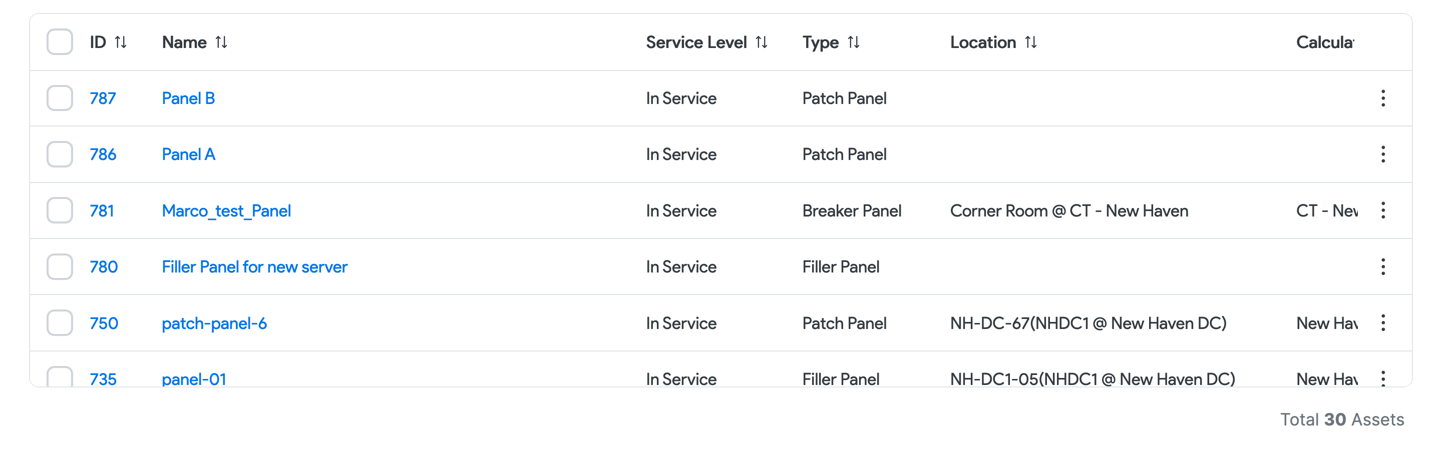
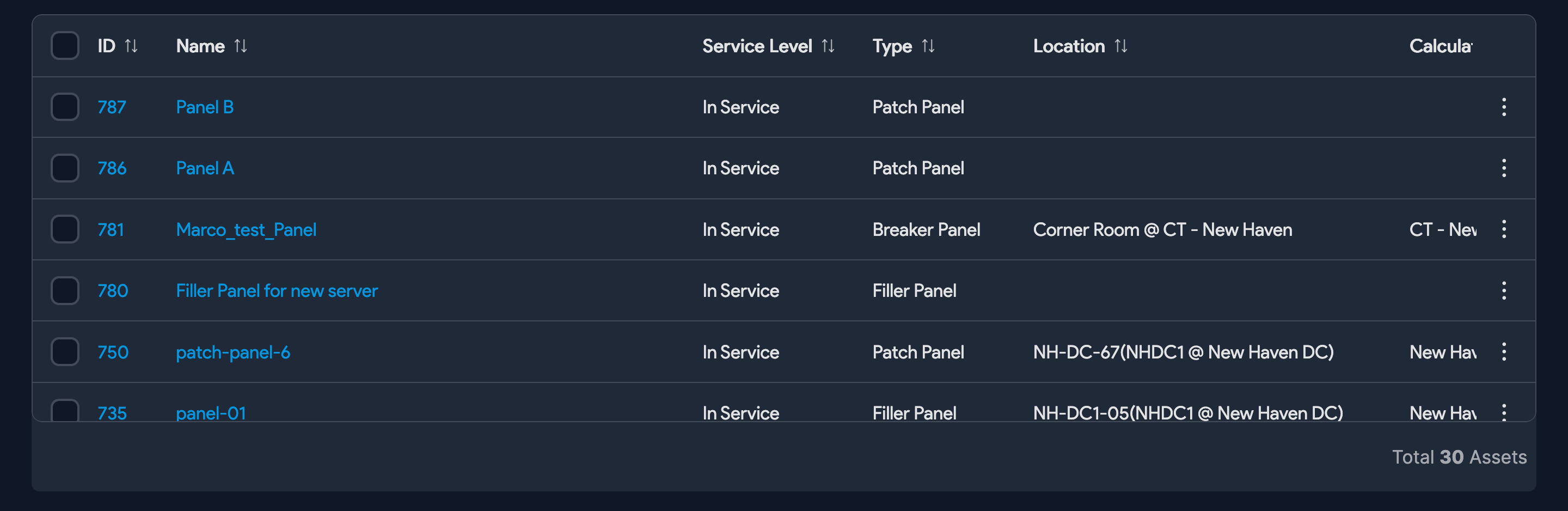
- Add the rows for the panel port number, panel ID (retrieved from the Asset list view, from APIs, or from hovering over the status bar), switch name, and switch port name.
- Import the XLS sheet.
Upon import, you can see the switch ports' connections on Panel A.
Patch Devices to Panel B

In this step, use the same sample Excel sheet downloaded in the step above.
The column layout is a little different and looks like this: number | patch_panel_id | device | obj_label1
Once you've added the values to Excel and imported the sheet, Panel B will show the following.
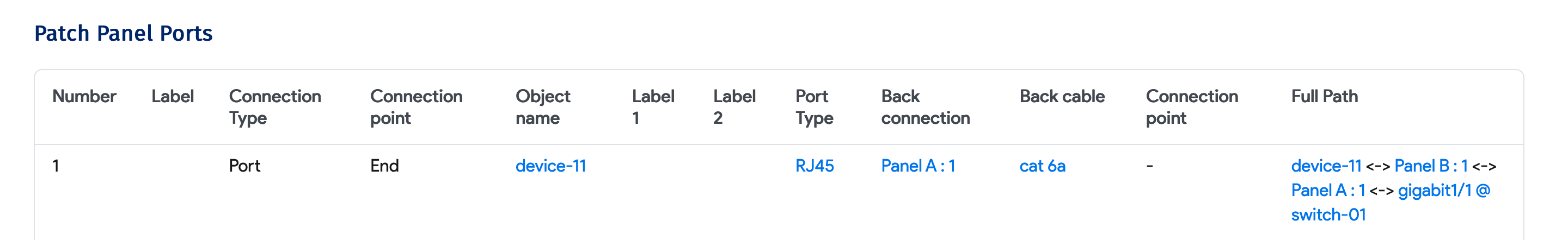
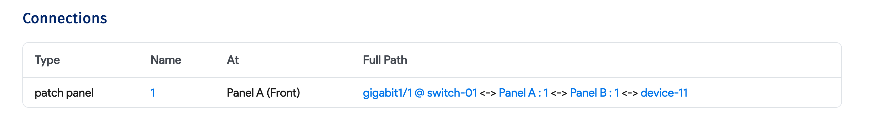
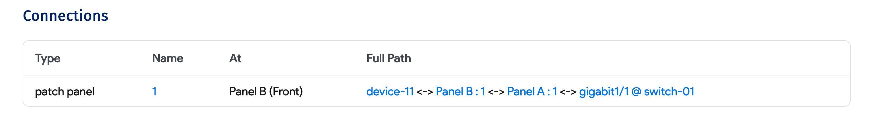
Patch Panel Layout
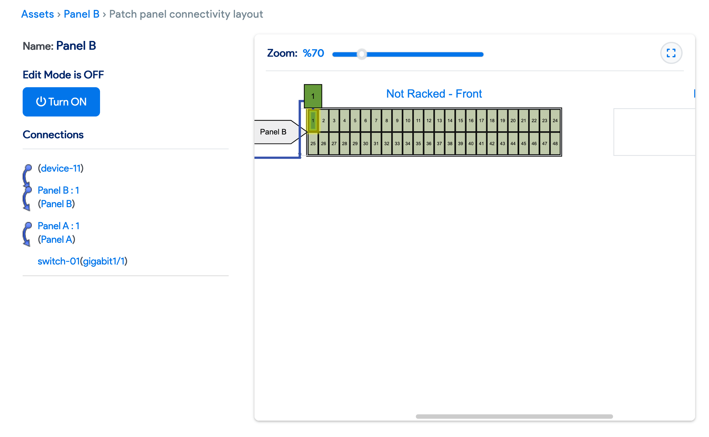
Now, if you go to Panel B's patch panel layout and hover over any port or device, you will see the full visual path for that port.
Switch Port Level Connectivity
You will see the patch panel connectivity from each switch port view as well.
Device Level Connectivity
Similarly, in the Device view and edit pages, you will see the patch panel connection under the Other tab.