Patch Panels and Cable Management
This page covers setting up patch panels, configuring connectivity, visualization options, and drag-and-drop connections.
Patch panels can be added as assets from Resources > Assets > All Assets.
Set Up Patch Panels
Create patch panel models and add patch panels to your assets.
Add a Patch Panel
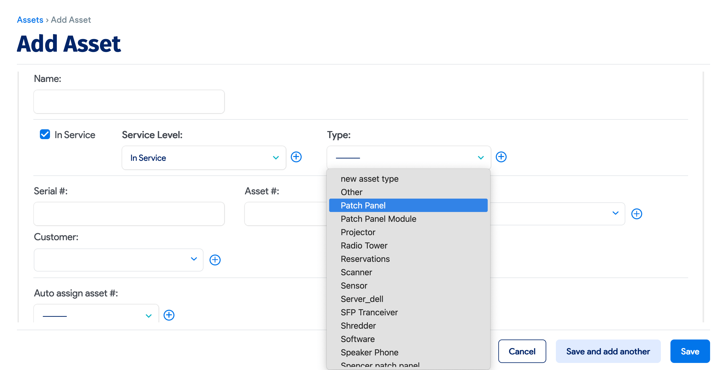
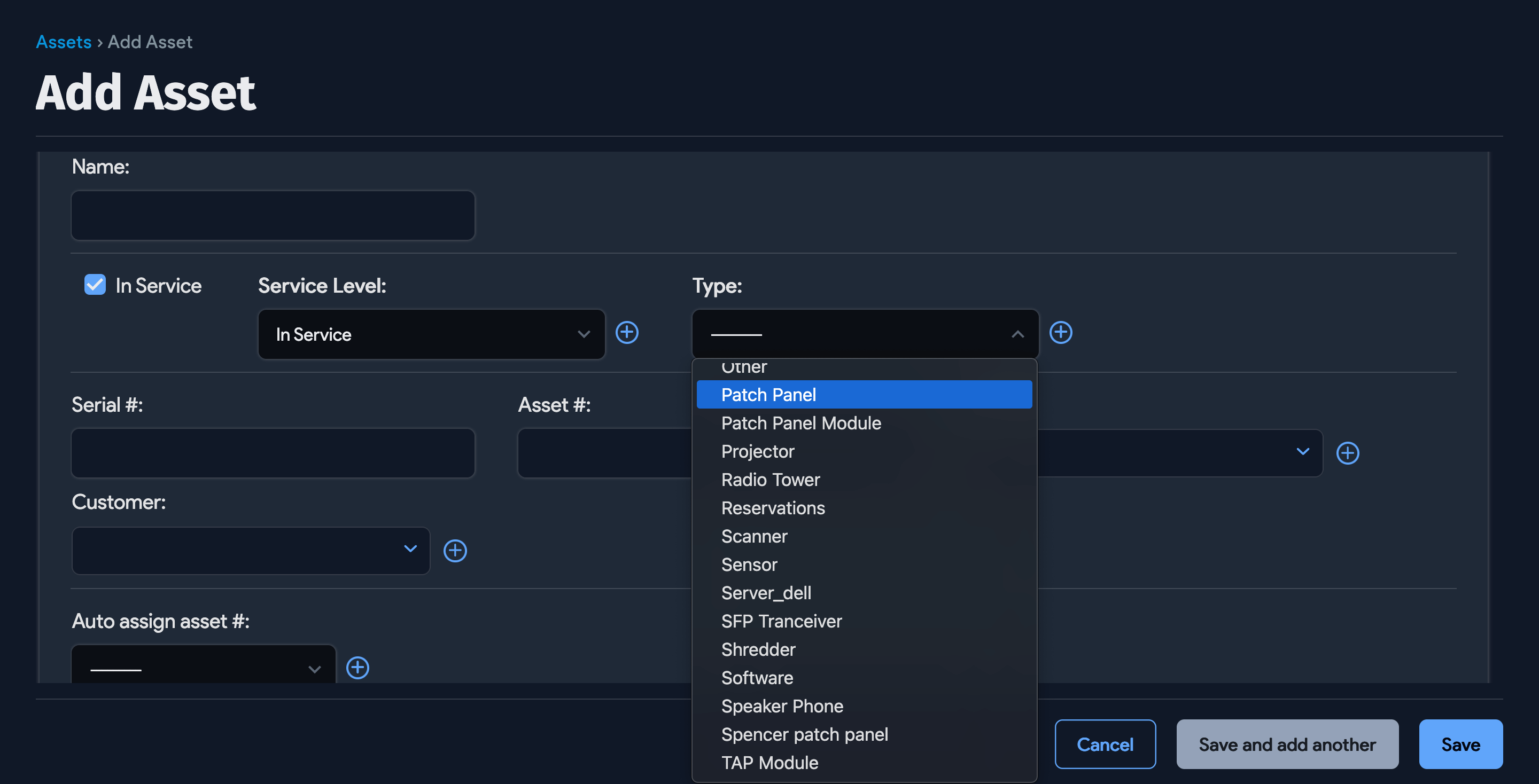
The system-defined asset type, Patch Panel, gives you the option to assign a patch panel model.
Ports and Properties Based on the Patch Panel Model
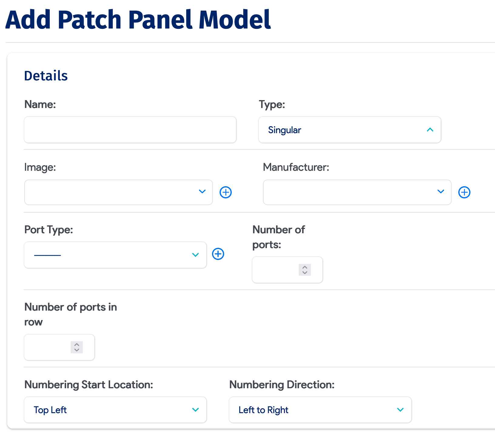
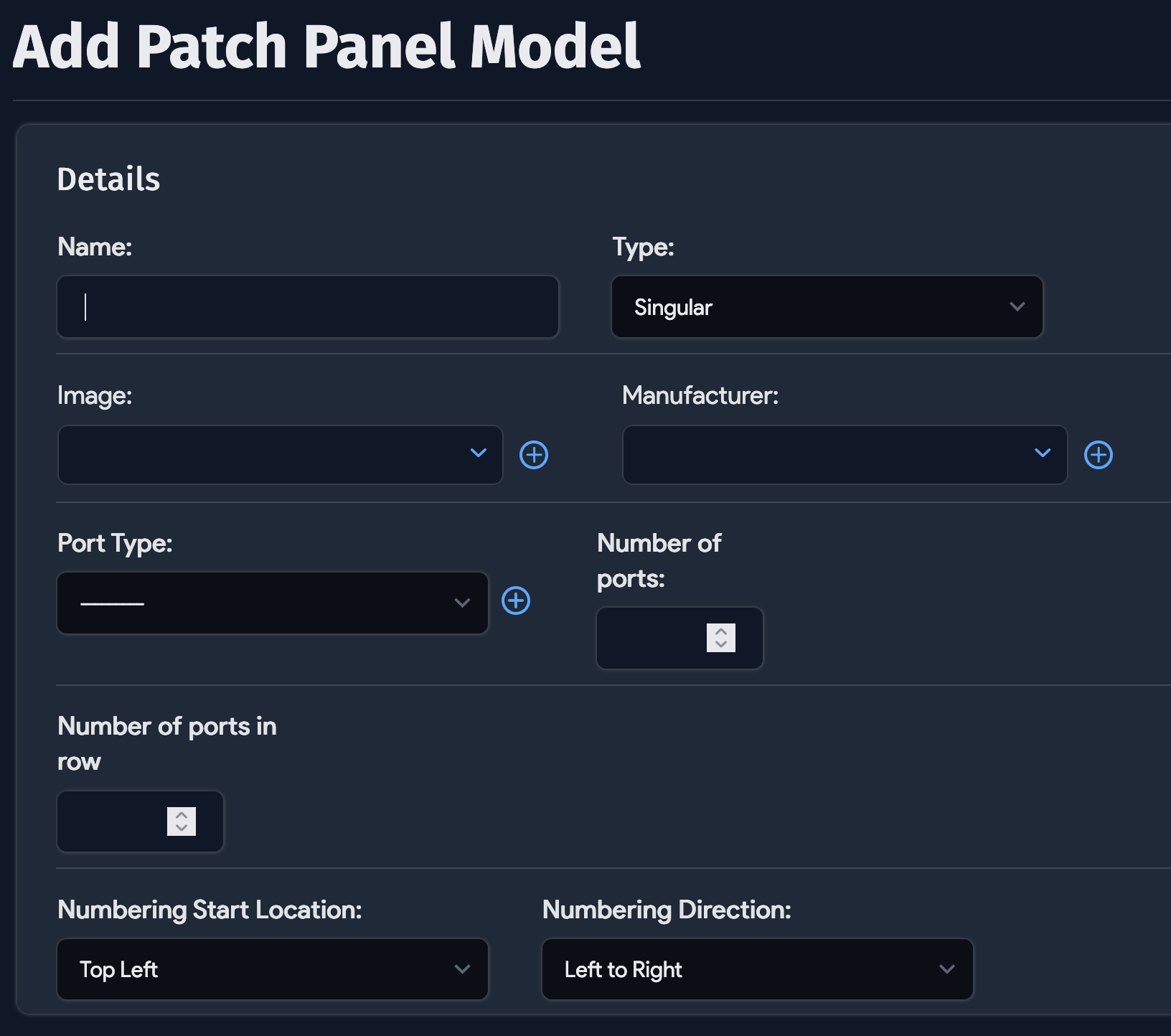
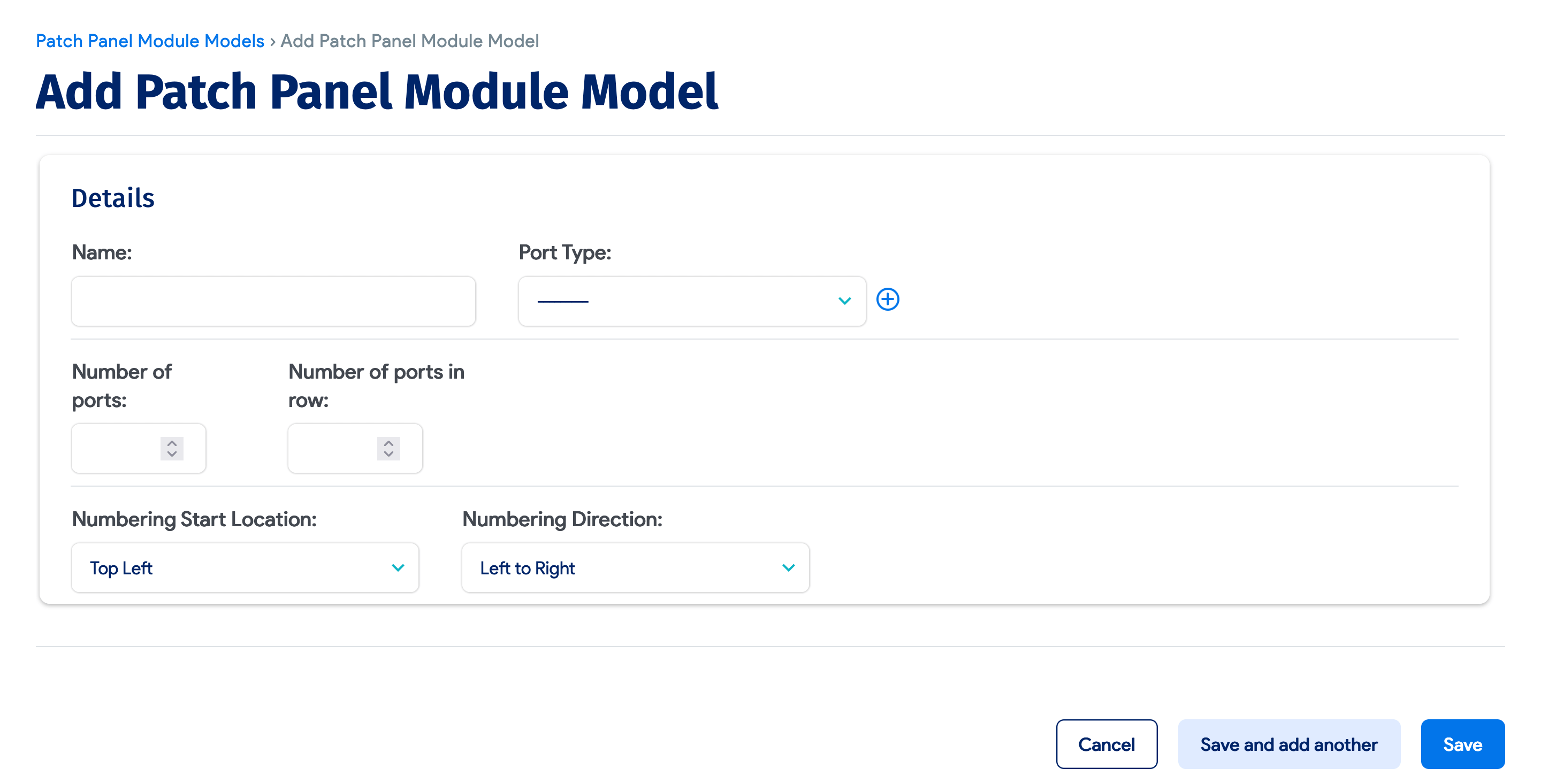
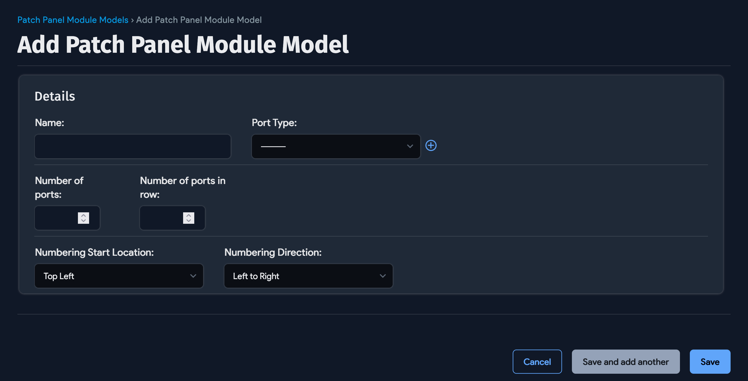
When creating a new patch panel model, you can enter:
- The Number of ports in the patch panel
- The Numbering Start Direction
- The Numbering Direction
- The Port Type
The first time a patch panel model is assigned to a patch panel, it takes the Number of ports entry shown above and creates and associates that number of ports with the patch panel. The image and vendor info from the model are also passed along to the patch panel if they are not already there.
If you have different cable types in the same patch panel, you should use Modular as the Type.
Modular Patch Panels
You can add modules to your patch panels and configure different port types or just modules. For a modular patch panel, you have the option to add modules. Ports for each module are created based on patch panel module models. All the module ports will appear in the original patch panel view.
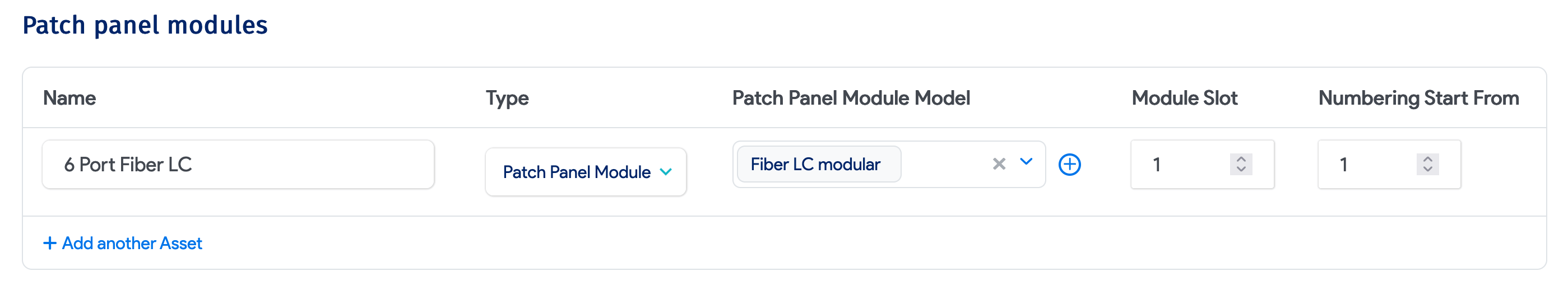
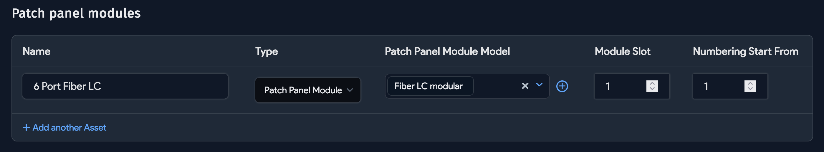
Once you have chosen a modular patch panel, you can add patch panel models as shown above the ports section.
Configure Connectivity
Connect patch panel ports to switches, devices, and other patch panels.
Patch Panel Connectivity
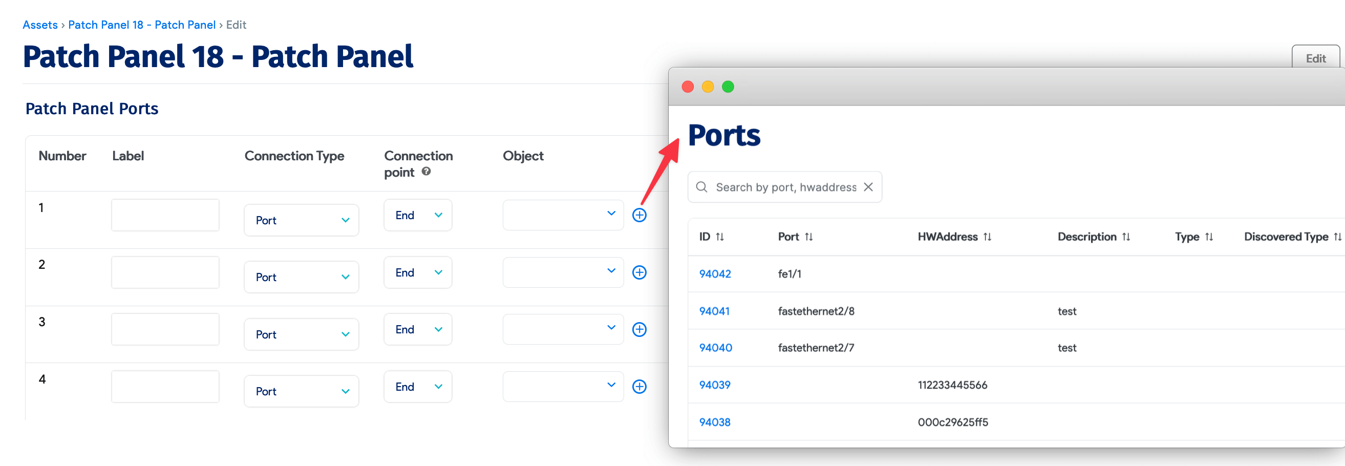
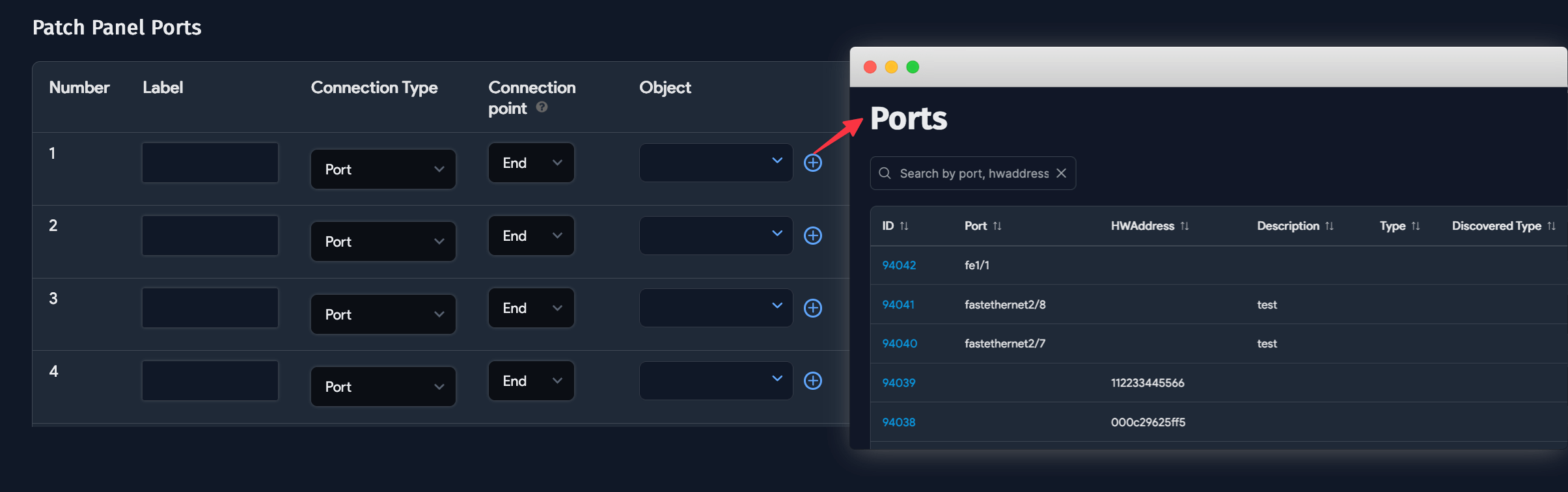
Once you have chosen a model and clicked the Save and continue editing button, you will see all the ports created.
Each port can be connected to one of the following:
- A switch port
- A device
- A patch panel port
If a patch panel is racked, by default, only the devices in that rack are shown. You can choose other devices as well. If a device is connected, you can also choose which MAC address on the device is connected using the Mac of device lookup button.
Individual Back Connectivity Per Port
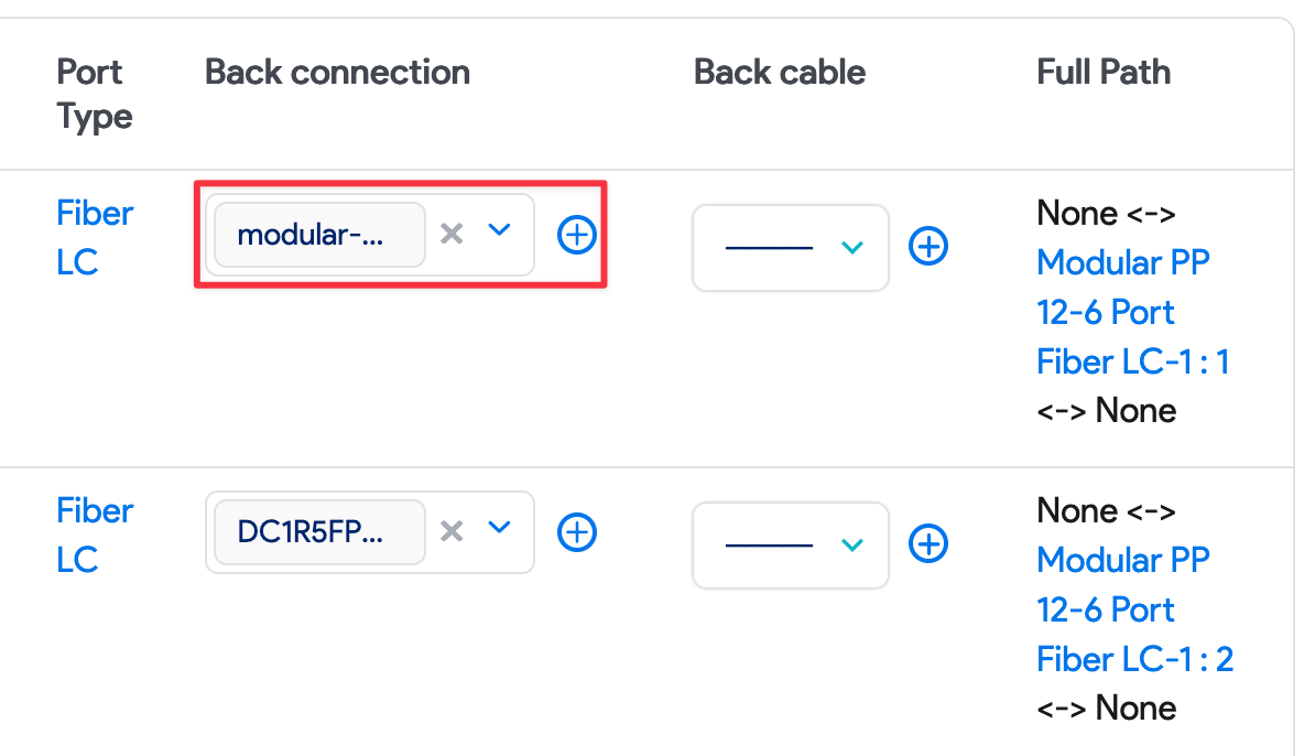
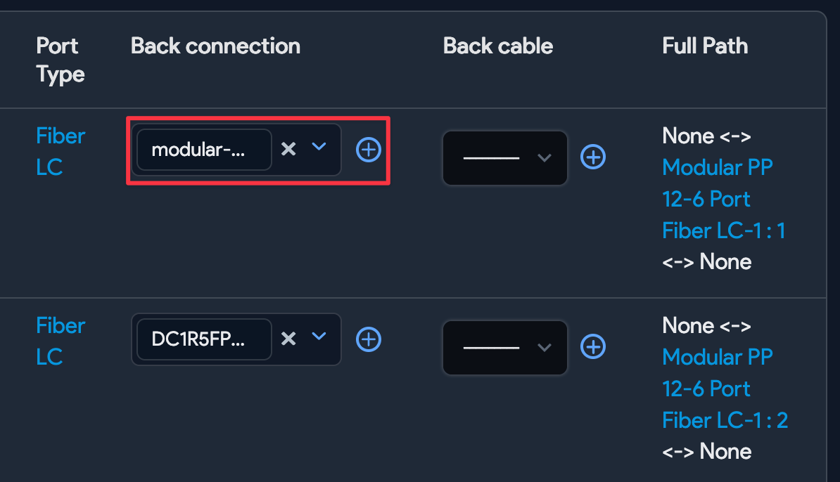
You can choose the individual Back connection per port and add a Back cable type for back connectivity with this option. You can add cable speed and other attributes for back connectivity for each port. In addition to the edit screens above, there are RESTful APIs and spreadsheet imports available for doing this more easily. There is also a bulk operations option for provisioning back connectivity, as discussed below.
Bulk Back Ports Connectivity
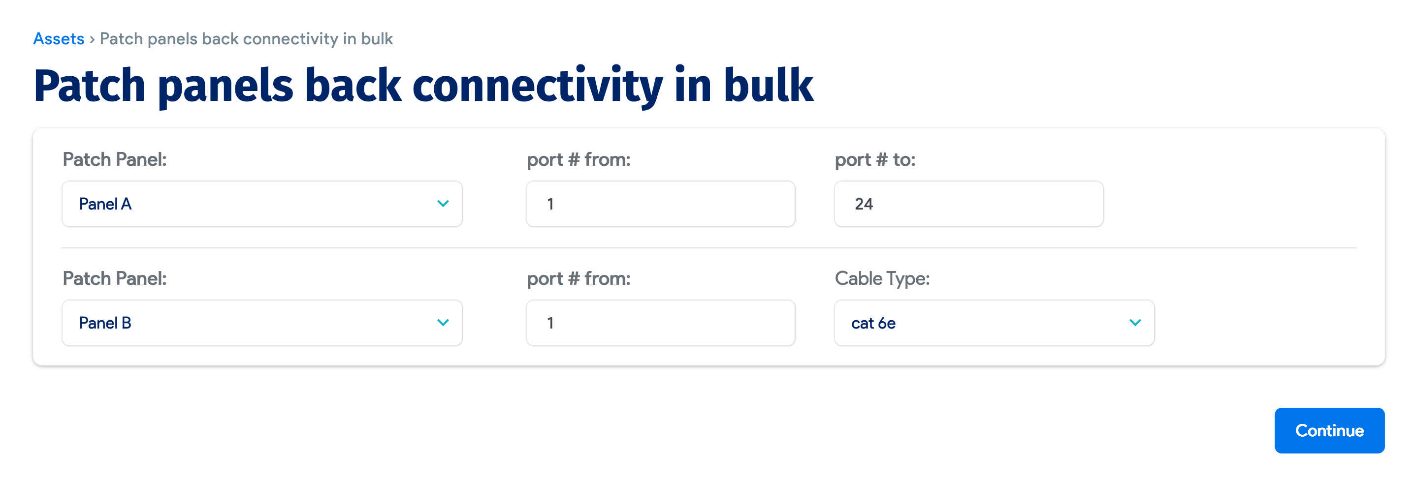
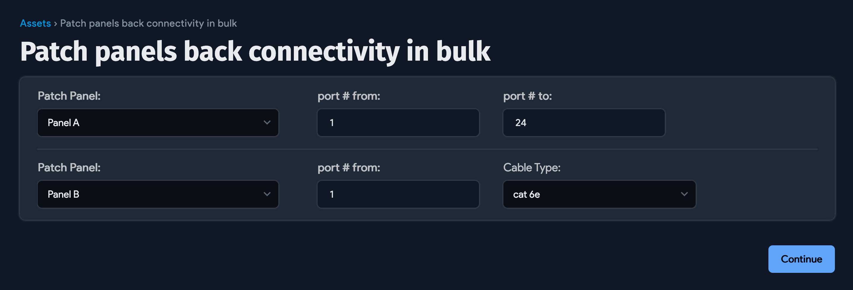
From Tools > Templates & Bulk Operations > Panel back connectivity, you can choose the patch panel, its modules (if any), starting port #, ending port #, patch panel and module, starting port #, and cable type. You can also provision back connectivity in bulk.
Visualization
View full connection paths and patch panel layouts.
Full Path Visualized
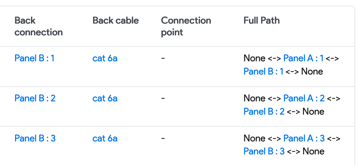
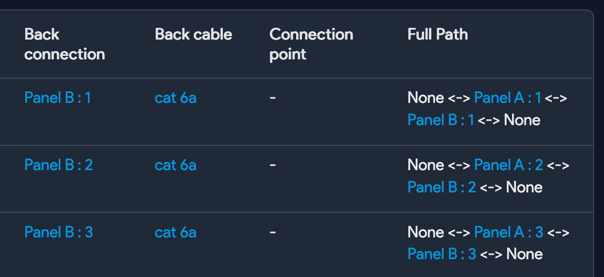
You can get full path details visualized in this table.
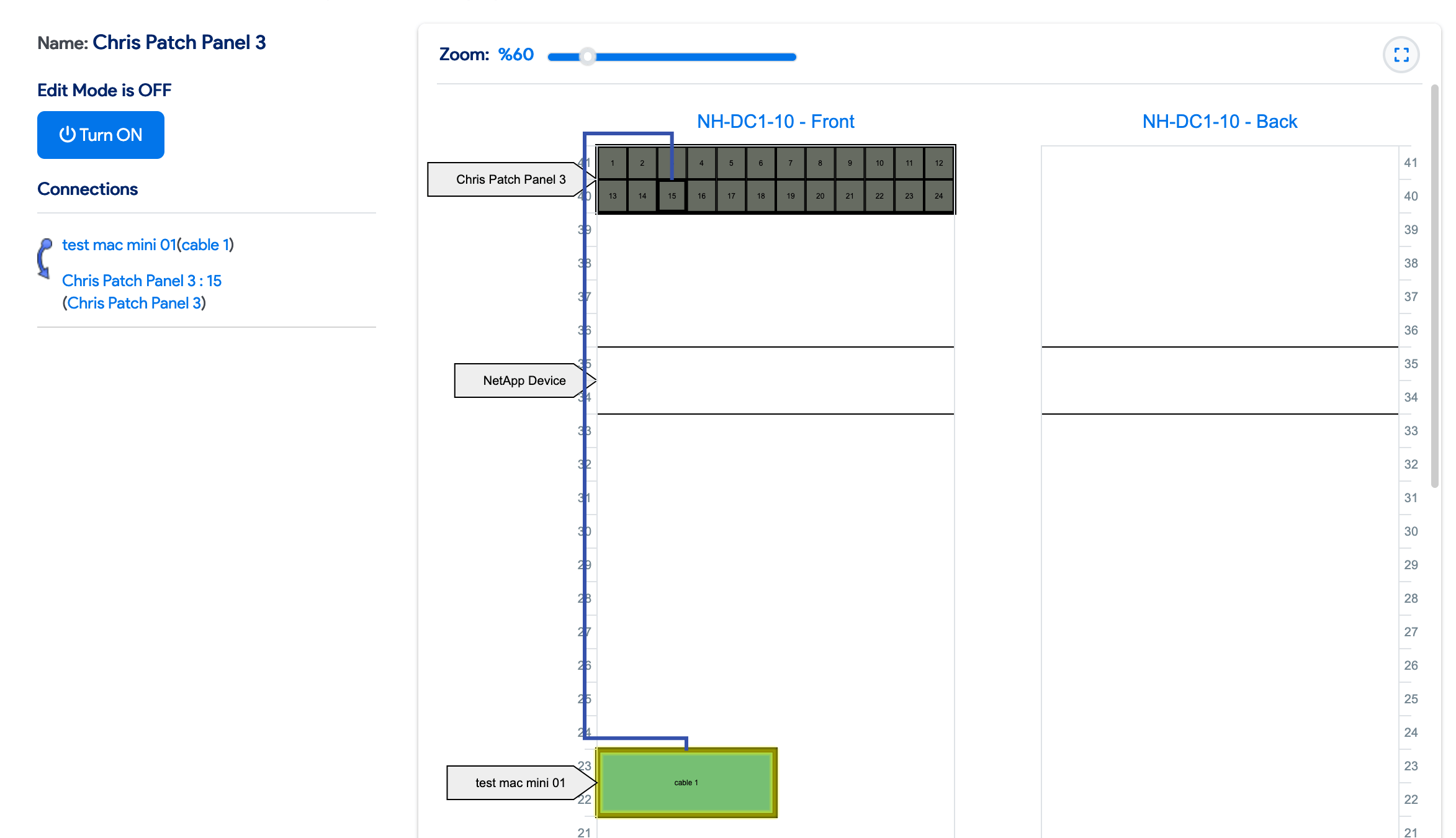
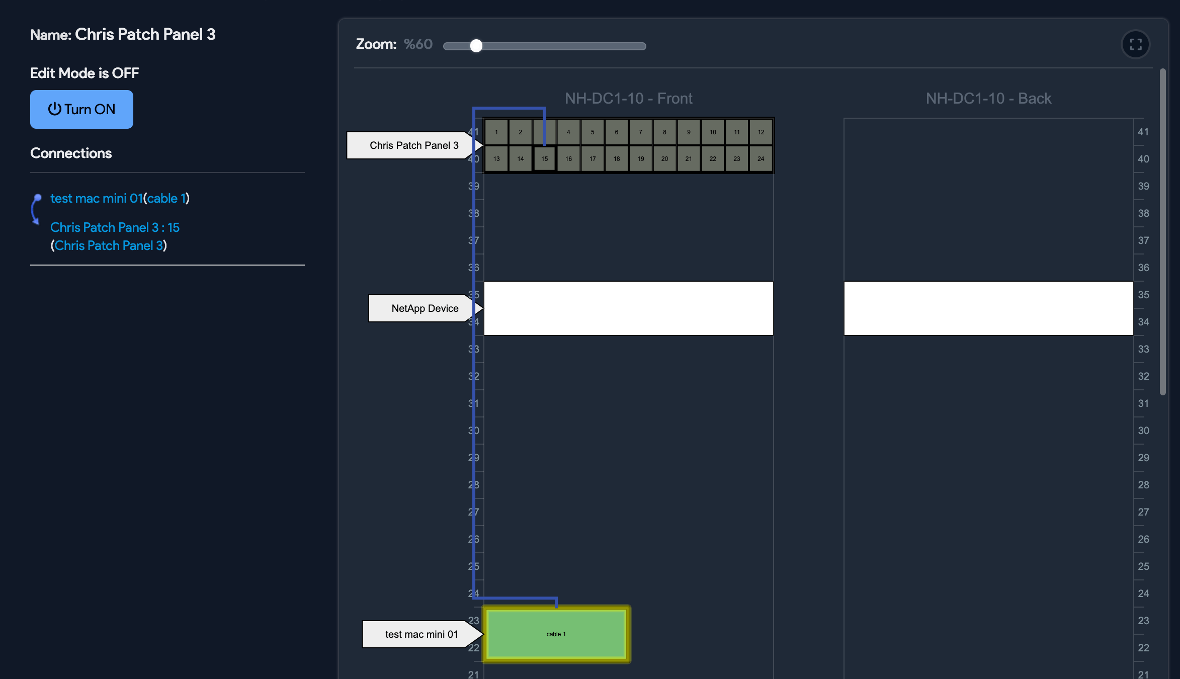
Patch Panel Layout
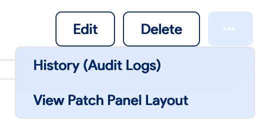
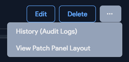
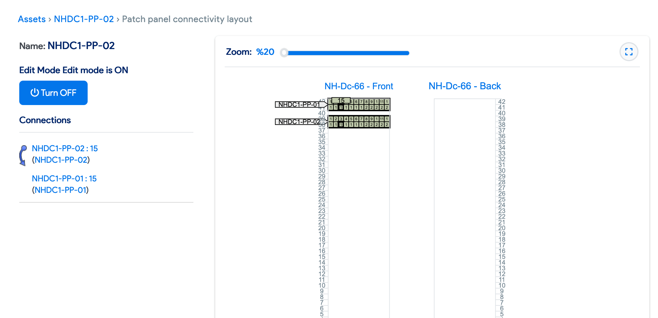
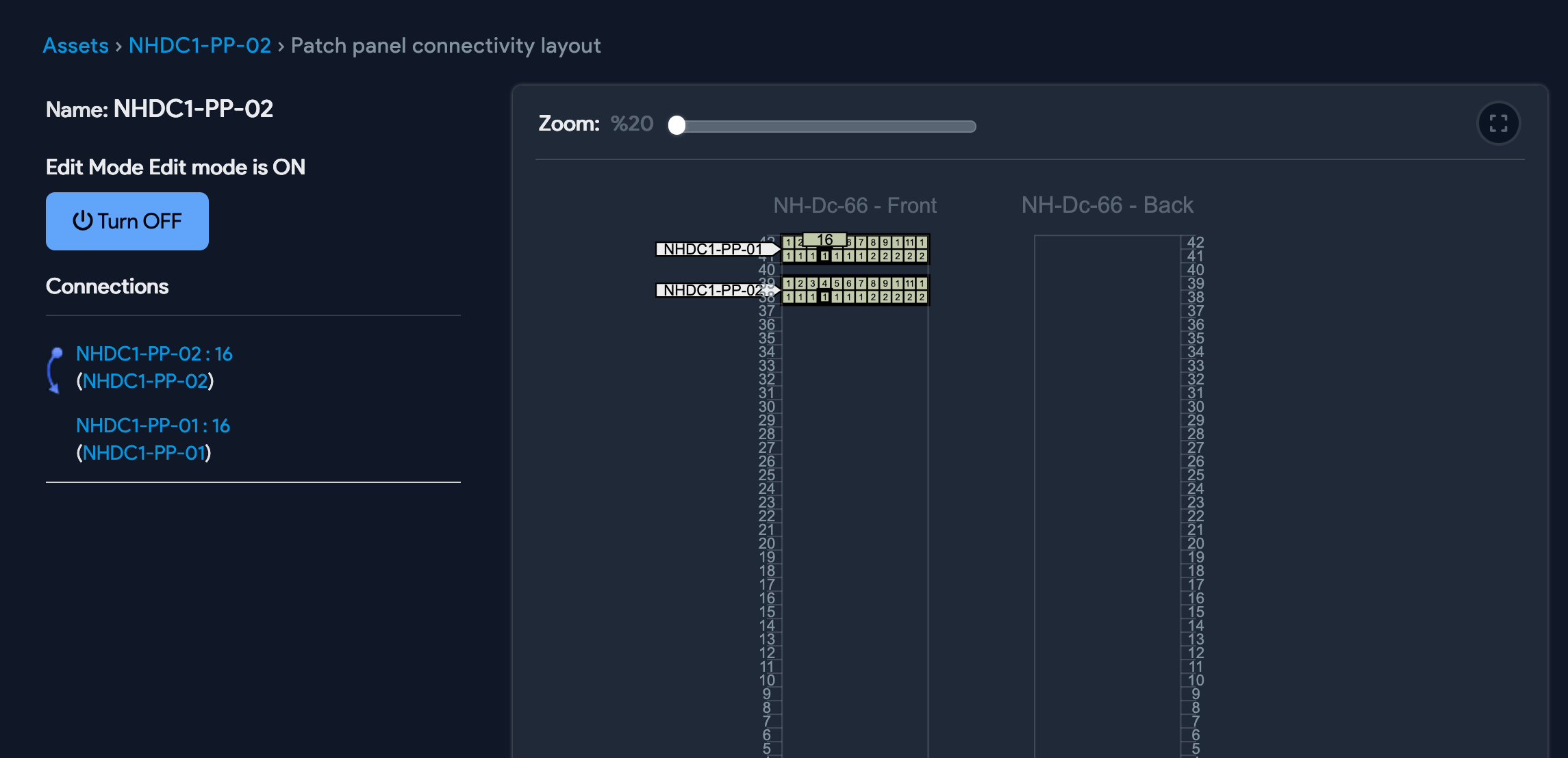
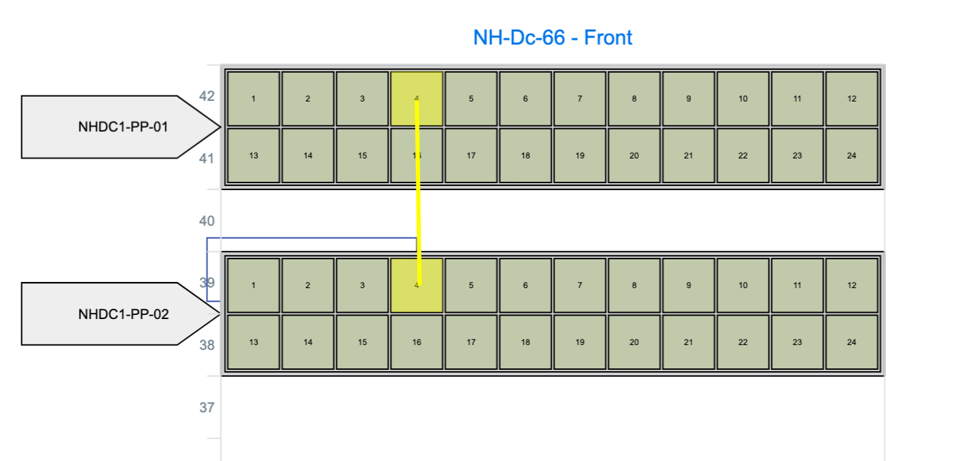
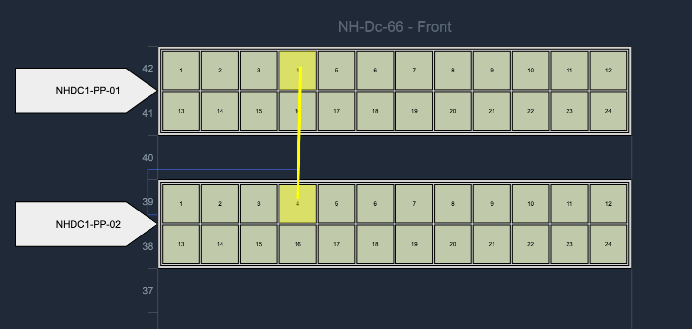
The view or edit page of that asset (the patch panel) adds a new View Patch Panel Layout button.
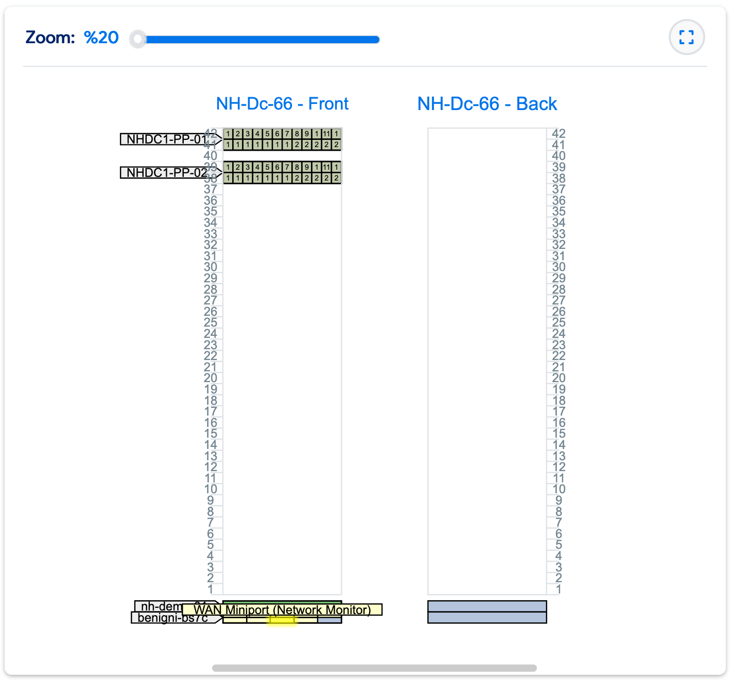
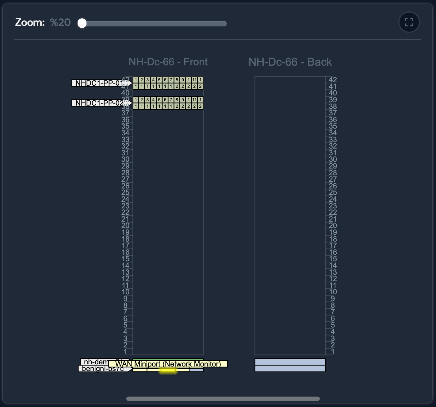
If the patch panel is connected to another patch panel, both panels are displayed side by side. Hovering over any port (or device) highlights the path and displays the text for that port and its connections. Each port is color-coded in the same way as in the port display.
Drag-and-Drop Connections
Use drag-and-drop to create and manage patch panel connections.
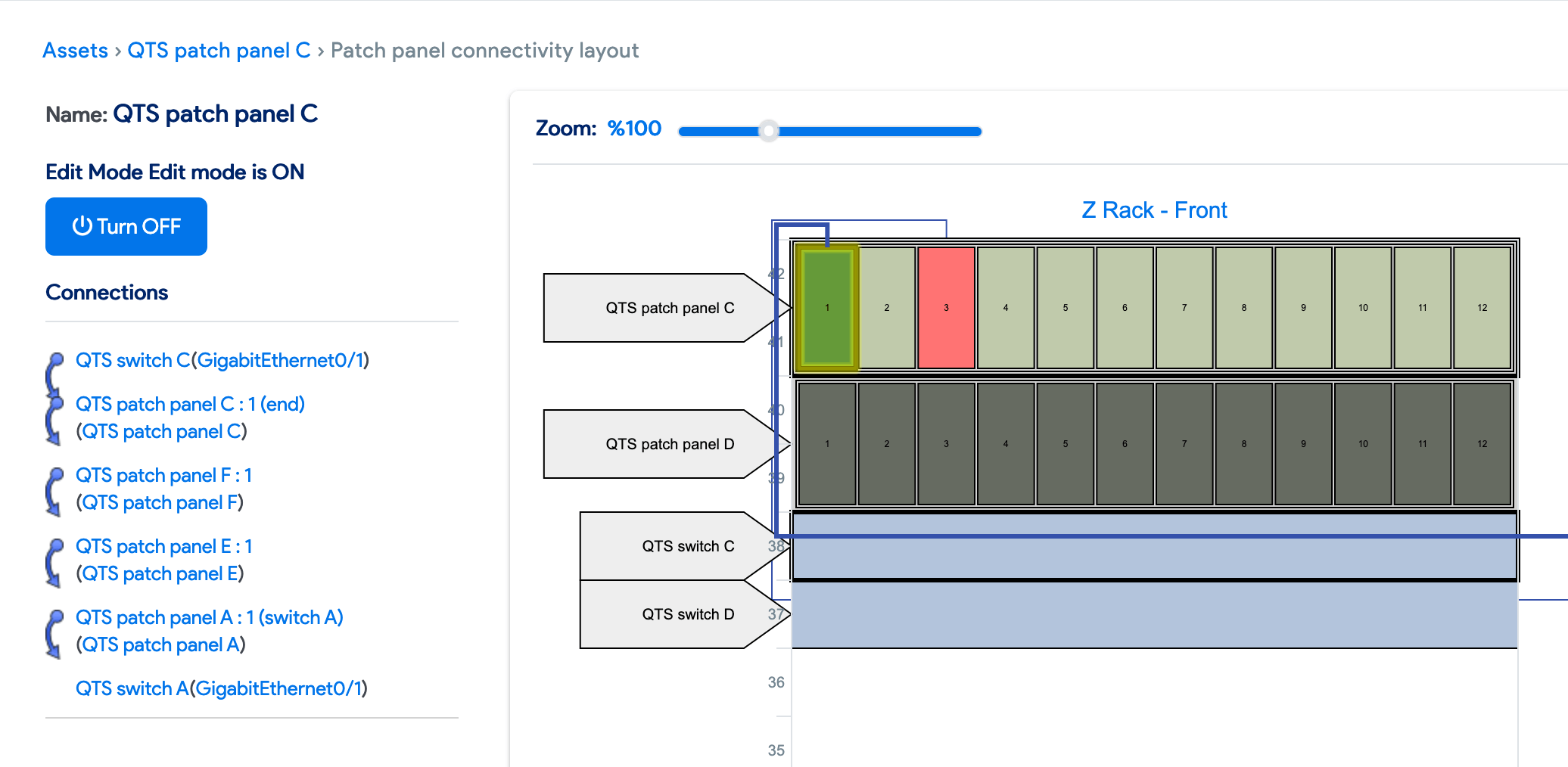
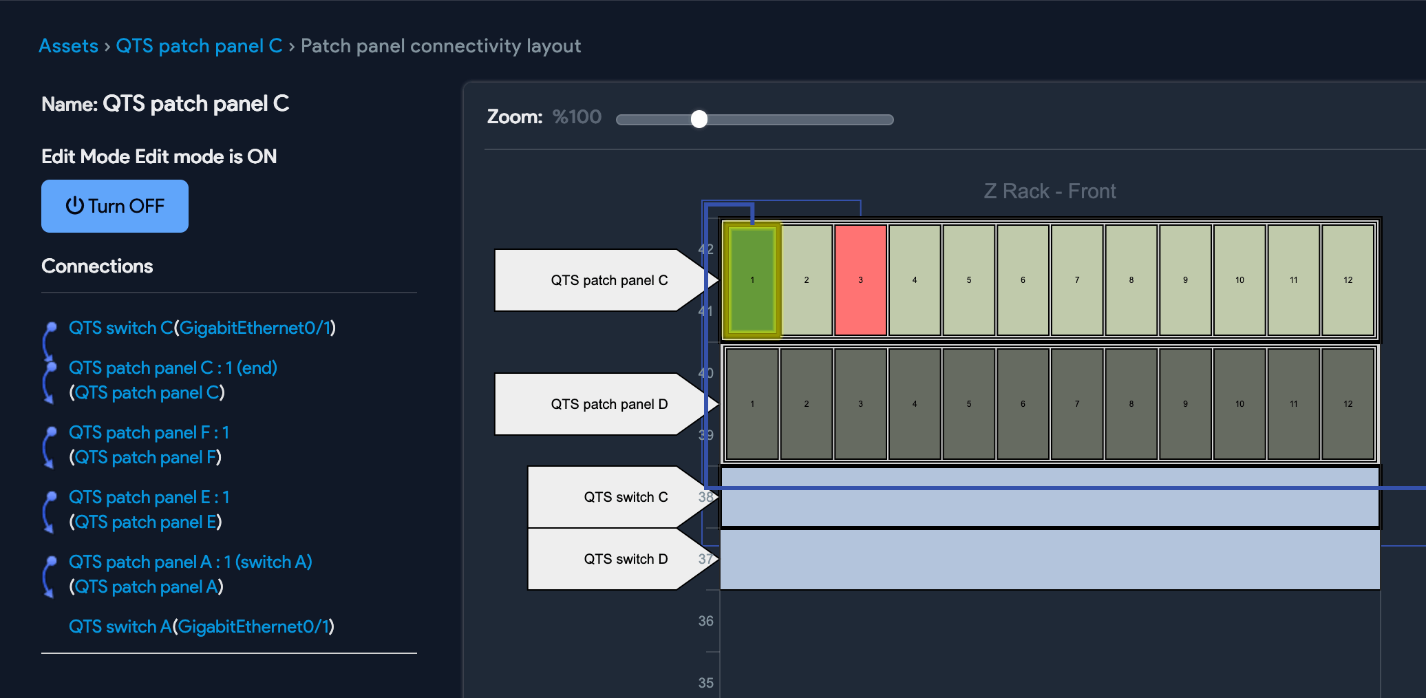
Create Connections With Drag-and-Drop
From the Patch Panel Layout page, you can turn on the edit mode and connect patch panel ports to other devices or switch ports by dragging a port to a device or another port. This makes it very easy to manage your patch panel connectivity and keep information up to date.
Drag-and-Drop for Switch Port
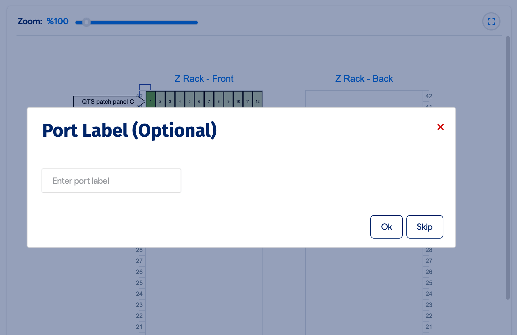
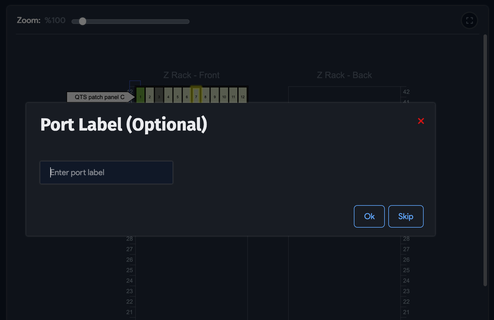
From the Patch Panel Layout page, you can also drag-and-drop switch ports to devices or to patch panel ports. When you do so, a popup appears, giving you the opportunity to enter a port label.
Direct Patch Panel Port to Patch Panel Ports Connections
You can add front patch panel connections to the ports of another patch panel via drag-and-drop.
Special Cases
Handle devices outside the rack, half-depth devices, and multi-hop connections.
Devices Outside the Rack
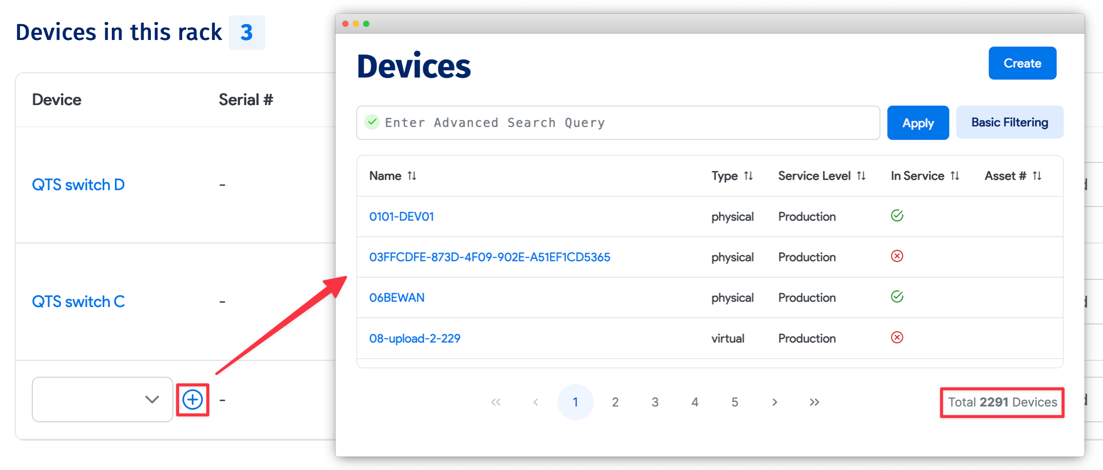
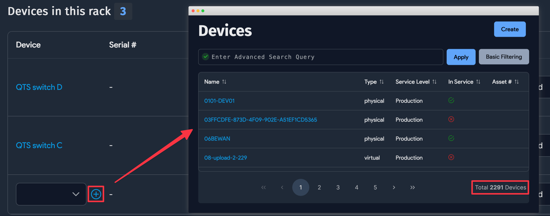
By default, only the devices in the same rack as the asset would show up. You can reset the filter by clicking on total devices, as shown above, and choose a device outside the rack. These are displayed on the left side of the patch panel, as shown below.

Half-Depth Devices
Half-depth devices are displayed side by side to show the cabling.
Multiple Hops or Patch Panels
If a connection spans multiple patch panels, it is displayed when you hover your cursor over that port (or connected device, switch port, etc.). It is displayed on the left side of the panel.